BUCK CONVERTER
Buck Converter
Definition: Buck Converter is a type of chopper circuit that is designed to perform step-down conversion of the applied dc input signal. In the case of buck converters, the fixed dc input signal is changed into another dc signal at the output which is of lower value. This means it is designed to produce a dc signal as its output that possesses a lower magnitude than the applied input.
It is sometimes called Step-down DC to DC Converter or Step-down Chopper or Buck Regulator.
Introduction
We have already discussed in our previous content that choppers are the circuits that are designed to perform the conversion of a fixed dc signal into an adjustable dc signal. It is mainly designed to increase or decrease the voltage level of the signal applied at its terminals.
There are various power semiconductor devices such as power BJT, power MOSFET, IGBT, GTO, etc. that acts as a switch in the chopper circuits. The use of thyristor is generally prohibited in chopper circuits and the reason behind the same is that in order to commutate a thyristor, an external commutation circuit is required. While power MOSFET or IGBT can be turned off by maintaining zero potential between the gate to source terminal for MOSFET or gate to collector terminal for IGBT.
We have mentioned in the beginning itself that choppers are designed to produce such a dc signal at the output which is more or less than that of the applied input signal. A buck converter is a type of chopper which is designed to generate a lower value at its output from the fixed dc input signal.
Operating Principle of Buck Converter
The figure given below shows the circuit representation of Buck Converter:
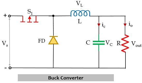
In the above figure, it is clearly shown that along with the power electronics solid-state device which acts as a switch for the circuit, there is another switch in the circuit which is a freewheeling diode. The combination of these two switches forms a connection with a low-pass LC filter in order to reduce current or voltage ripples. This helps in generating regulated dc output. A pure resistor is connected across this whole arrangement that acts as a load of the circuit.
The whole operation of the circuit takes place in two modes. The first mode is the one when the power MOSFET i.e., switch S1 is closed.
In this mode of operation, switch S1 is in closed condition thus allows the flow of current to take place through it.
Buck Converter
Definition: Buck Converter is a type of chopper circuit that is designed to perform step-down conversion of the applied dc input signal. In the case of buck converters, the fixed dc input signal is changed into another dc signal at the output which is of lower value. This means it is designed to produce a dc signal as its output that possesses a lower magnitude than the applied input.
It is sometimes called Step-down DC to DC Converter or Step-down Chopper or Buck Regulator.
Introduction
We have already discussed in our previous content that choppers are the circuits that are designed to perform the conversion of a fixed dc signal into an adjustable dc signal. It is mainly designed to increase or decrease the voltage level of the signal applied at its terminals.
There are various power semiconductor devices such as power BJT, power MOSFET, IGBT, GTO, etc. that acts as a switch in the chopper circuits. The use of thyristor is generally prohibited in chopper circuits and the reason behind the same is that in order to commutate a thyristor, an external commutation circuit is required. While power MOSFET or IGBT can be turned off by maintaining zero potential between the gate to source terminal for MOSFET or gate to collector terminal for IGBT.
We have mentioned in the beginning itself that choppers are designed to produce such a dc signal at the output which is more or less than that of the applied input signal. A buck converter is a type of chopper which is designed to generate a lower value at its output from the fixed dc input signal.
Operating Principle of Buck Converter
The figure given below shows the circuit representation of Buck Converter:
In the above figure, it is clearly shown that along with the power electronics solid-state device which acts as a switch for the circuit, there is another switch in the circuit which is a freewheeling diode. The combination of these two switches forms a connection with a low-pass LC filter in order to reduce current or voltage ripples. This helps in generating regulated dc output. A pure resistor is connected across this whole arrangement that acts as a load of the circuit.
The whole operation of the circuit takes place in two modes. The first mode is the one when the power MOSFET i.e., switch S1 is closed.
In this mode of operation, switch S1 is in closed condition thus allows the flow of current to take place through it.
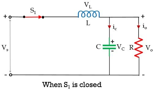
Initially when a fixed dc voltage is applied across the input terminal of the circuit then in the closed condition of switch S1 current flows in the circuit in the manner shown above. Due to this flowing current, the inductor in the path stores energy in the form of a magnetic field. Also, there is a capacitor in the circuit and current flows through it also, therefore, it will store the charge and the voltage across it will appear across the load.
However, due to Lenz’s law, the energy stored within the inductor will oppose the cause which has produced it and so an induced current will get generated and the polarity across the inductor will get reversed.
Here the total time period is a combination of Ton and Toff time.
T = Ton + Toff
The duty cycle is written as:
![]()
On applying KVL, in the above-given circuit,

Also,
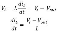
When S1 is in closed condition then Ton = DT thus Δt = DT. Therefore, we can write,
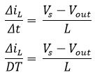
Hence,
The above equation represents the change in current through the circuit when switch S1 is closed.
Now, the second mode of operation takes place when switch S2 is closed and S1 gets open. However, you must be thinking about how automatically, the switch S2 will be closed. So, as we have discussed that the inductor in the circuit will store the energy so, once S1 will get open the inductor in the circuit will start acting as the source.
In this mode, the inductor releases the energy which is stored in the previous mode of operation. As we have discussed that the polarity of the inductor will get reversed therefore this causes the freewheeling diode to come in a forward-biased state which was earlier present in a reverse-biased state due to the applied dc input.
Due to this, the flow of current takes place in a way as shown below:
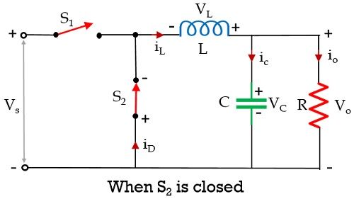
This flow of current will take place till the time the stored energy within the inductor gets completely collapsed. As once the inductor gets completely discharged, the diode comes in reverse biased condition leading to cause opening of switch S2, and instantly switch S1 will get closed and the cycle continues.
Now, let us apply KVL, in the above circuit,

Since, we know,
T = Ton + Toff
T = DT + Toff
Toff = T – DT
Toff = (1 – D)T

Toff = Δt = (1 – D)T

So,
This equation represents the rate of change in current through the inductor when the switch S1 is open.
As we know that the net change of current through the inductor in one complete cycle is zero. Thus,

On simplifying,
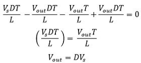
The figure given below represents the waveform representation of Buck Converter:
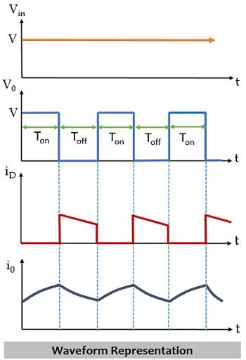
Hence, we can say, buck converters are used to provide a lower value of dc signal from a fixed dc input.


Comments
Post a Comment